- 您现在的位置:买卖IC网 > Sheet目录314 > AT91SAM9M10-G45-EK (Atmel)KIT EVAL FOR AT91SAMG45/9M10
Board Description
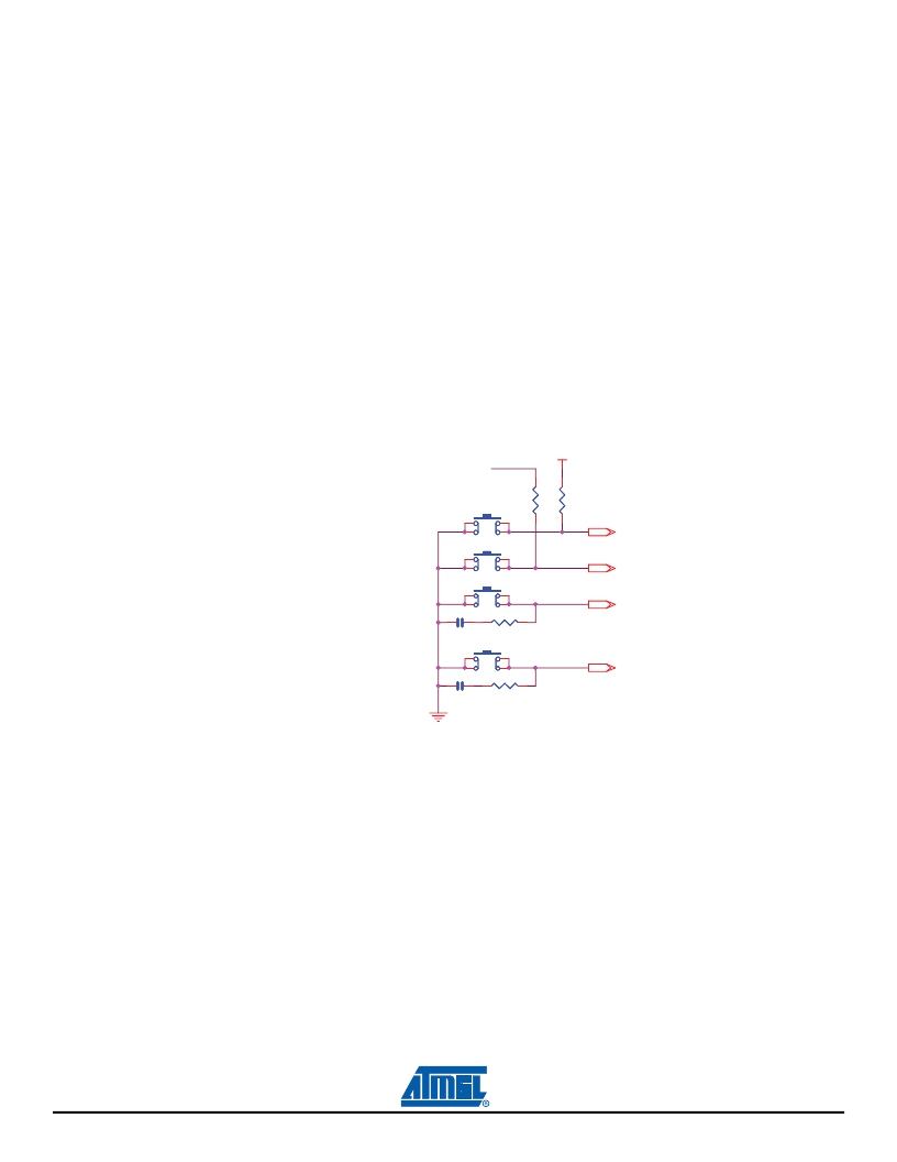
4.2.14
Push Buttons
The SAM9M10-G45-EK is equipped with two system push buttons, two user push buttons and one joy-
stick. The push buttons consist of momentary push button switches mounted directly to the board. When
any switch is depressed, a low (zero) appears at the associated input pin.
System push buttons:
– Reset, perform system reset
– Wakeup, perform system wake up
User push button:
– Right click
– Left click
Joystick:
– One touch, 5-way switching,
– Normally open momentary contacts,
– Push down to select in any position.
Figure 4-20.
Push Buttons
VDDBU
3 V 3
R2 3
R24
BP1
100k
1k
NR S T
WAKE UP
BP2
BP4
NR S T
WAKE UP
RIGHT CLICK
C 3 1
10n
R27
100R
PB7
BP5
4.2.15
Expansion Slot
LEFT CLICK
C 3 7
10n
R29
100R
PB6
GPIO1 & GPIO2, LCD signals (PIO E) are routed to the connectors extension J23
All I/Os of the SAM9M10 Image Sensor Interface are routed to connectors J17
Touch screen signals and analog I/O are connected to J18
This allows the developer to extend the features of the board by adding external hardware components
or boards.
4-22
6495B–ATARM–21-Apr-10
AT91SAM9M10-G45-EK User Guide
发布紧急采购,3分钟左右您将得到回复。
相关PDF资料
AT91SAM9RL-EK
KIT EVAL FOR AT91SAM9RL
AT91SAM9X35-EK
KIT EVAL FOR AT91SAM9X35
AT91SAM9XE-EK
KIT EVAL FOR AT91SAM9XE
AT93C46D-TH-T
IC EEPROM 1KBIT 2MHZ 8TSSOP
AT93C46E-TH-T
IC EEPROM 1KBIT 2MHZ 8TSSOP
AT93C46Y6-10YH-1.8
IC EEPROM 1KBIT 2MHZ 8DFN
AT93C56A-10TU-2.7
IC EEPROM 2KBIT 2MHZ 8TSSOP
AT93C86AY6-10YH-1.8
IC EEPROM 16KBIT 2MHZ 8MAP
相关代理商/技术参数
AT91SAM9M11
制造商:ATMEL 制造商全称:ATMEL Corporation 功能描述:AT91 ARM Thumb-based Microcontrollers
AT91SAM9M11B-CU
制造商:Atmel Corporation 功能描述:BGA, GREEN, IND TEMP,CRYPTO MRL B - Bulk 制造商:Atmel Corporation 功能描述:IC MCU ARM9 64KB ROM 324TFBGA 制造商:Atmel Corporation 功能描述:MCU 32BIT ARM9 324TFBGA 制造商:Atmel Corporation 功能描述:MCU, 32BIT, ARM9, 324TFBGA 制造商:Atmel Corporation 功能描述:BGA, Green, IND TEMP,CRYPTO MRL B
AT91SAM9M11-CU
功能描述:ARM微控制器 - MCU IND TEMP MRL A
RoHS:否 制造商:STMicroelectronics 核心:ARM Cortex M4F 处理器系列:STM32F373xx 数据总线宽度:32 bit 最大时钟频率:72 MHz 程序存储器大小:256 KB 数据 RAM 大小:32 KB 片上 ADC:Yes 工作电源电压:1.65 V to 3.6 V, 2 V to 3.6 V, 2.2 V to 3.6 V 工作温度范围:- 40 C to + 85 C 封装 / 箱体:LQFP-48 安装风格:SMD/SMT
AT91SAM9N12-CU
功能描述:ARM微控制器 - MCU BGA Grn IT MRL A
RoHS:否 制造商:STMicroelectronics 核心:ARM Cortex M4F 处理器系列:STM32F373xx 数据总线宽度:32 bit 最大时钟频率:72 MHz 程序存储器大小:256 KB 数据 RAM 大小:32 KB 片上 ADC:Yes 工作电源电压:1.65 V to 3.6 V, 2 V to 3.6 V, 2.2 V to 3.6 V 工作温度范围:- 40 C to + 85 C 封装 / 箱体:LQFP-48 安装风格:SMD/SMT
AT91SAM9N12-CUR
制造商:Atmel Corporation 功能描述:BGA,GREEN,IND TEMP,MRL A,T&R 制造商:Atmel Corporation 功能描述:BGA,GREEN,IND TEMP,MRL A,T&R - Tape and Reel 制造商:Atmel Corporation 功能描述:IC MCU ARM9 ROM 217BGA 制造商:Atmel Corporation 功能描述:BGA GREEN,IND TEMP,MRL A
AT91SAM9N12-EK
功能描述:开发板和工具包 - ARM EVAL KIT SAM9N12
RoHS:否 制造商:Arduino 产品:Development Boards 工具用于评估:ATSAM3X8EA-AU 核心:ARM Cortex M3 接口类型:DAC, ICSP, JTAG, UART, USB 工作电源电压:3.3 V
AT91SAM9R64
制造商:ATMEL 制造商全称:ATMEL Corporation 功能描述:Thumb Microcontrollers
AT91SAM9R64_09
制造商:ATMEL 制造商全称:ATMEL Corporation 功能描述:AT91 ARM Thumb Microcontrollers